
 |
| What is old is new again! |
So for the uninitiated, this is how a Spyder works:


The pump handle brings both the bolt and striker back to firing position. Pump handle moves forward and brings a ball into place. Pulling the trigger will release the striker into the valve and bring air into the upper tube to launch the ball. Note how there is no blowback action that will reset the striker.
This is the challenge.
Following so many resources on the web, the primary source is with Vike's guide. With this and the variety of other guides, there are no set instructions on how to get your pump handle created, or how to fabricate your pump rod, or if you need a backblock. They give you concepts and examples of existing completed projects. They make you think about making calculated decisions about your build.
I.
Love.
This.
Similar to those that lived through the Golden Age of Paintball with Spyder owners, tricking out and individualizing your marker was a right of passage. I just saw this as another avenue to continue this same path with the piles of Spyders I've customized since the late 90s. This is where my newer skills come out to shine.
3D Design
 |
| First printed version of the backblock |
The Backblock
Before I took on the design work for the pump handle, I decided to go a bit easier with making the backblock. Strategically, this was the best thing to do since I had to measure travel of the rear cocking bolt. The process of measuring the travel by slowly pulling the bolt back and waiting for the sear to click, ready for cycling, over and over was imperative to making sure that the spacing was proper. Also taking provisions on how far forward the bolt moves to engage the striker to the poppet was the other thing to measure repeatedly. This brings us to the thickness shown in the pic to the right. That has never changed with all the newer versions. Along with that, the cotter pin location never moved!Pump Arm Rod Guides
Next up was the gratuitously large pump arm connecting rods guides. Some decisions had to be made when designing for the the pump arm connecting rods. Does it needed to be rods or rod? I didn't want to multiply the stress on the backblock only at 1 point of contact. (Yes, I designed it with 2 lobes for 2 pump rods...) Obviously, I decided on 2 rods. Original designs carried almost all the way to the end included roll pins to guide 1/8" steel rods. It seemed to slide without any issues. (I jinxed myself. More on that later...)Pump Handle
 |
| Almost final version! |
3D Printing
 |
| Top - Original Twisted pump handle Middle - 2 backblocks and part of the railguide Bottom - Soooo many pump handles! |
 |
| Who doesn't love an animated gif? |
Working the Metal
Slotting the striker
The last 2 items to make this thing a reality was to mod the striker and the poppit valve stem. Hand milling out the hardened steel striker wasn't an easy task. I purchased a drill press vise to put on the deck of my press. Mounted the vise, clamped in the piece and put in the right sized drill bit. This just wasn't working. No amount of cutting oil and changing out bits gained me any type of headway in dropping holes into this piecer. Other people on the web state that it's pretty impossible to do it this way and to just use reinforced cutting wheels on a Dremel. Switched to that and about 20 minutes later, I had striker with a hogged out channel for the bolt to ride along, but still act independently! (OMG, we are so close!)
Modifying the vertical ASA
Having the tools to do the mod, I drilled out the restrictive brass filter and widened out the whole air path for lower pressure operation. The front face of the ASA was drilled and tapped for the guide rod and return springs.Removing blowback
Last major step in this project is to mod the poppit valve stem to all the air routes up through the valve into the upper tube to launch the ball. This will also eliminate the blowback so the striker doesn't automatically cycle back for the next trigger pull. Sources say that you can buy a new valve assembly from a set of specific Autococker aftermarket parts or you can just use JB Weld and sand it down. I went with the latter with a twist! I ended up using the mini lathe that I purchased earlier this year to make bentwood rings! I slathered the epoxy on the flattened side of the pin and let it set overnight. The next day, I chucked it in the lathe and gently shaved it down with precision.Test Run
 |
| Successful day at The Siege! |
Embracing The Aesthetics
 |
| Sanded, Stained, Painted. Just needs a few topcoats! |
The Reveal
For about 2 months of work and loads of iterations, Project: Spump in it's current form!
There are still items to change, but this is how it will stay for some time. The biggest change will be the rail guides to lower the amount of material used and the location. The pump handle has already gone through some additional changes but won't be printed till this one hits critical failure. Below is a list of the primary parts used for this build.
Body Update:
I've been sitting on a donor Icon X for project parts. Since it's a 100% Spyder clone, it just made sense. It still houses all my mods but also allows me to delete the rail guide. (After shooting it for more than a year, the dual pump arm setup really didn't need the big, chunky, rail guide.) This body swap gives me vert feed and a ball detent. In time, I'll swap the plastic sight rail for a 3D printed Phantom Picatinny rail too.

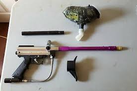
Build List
- Body -
Spyder CompactIcon X Vert Feed Body - Vertical ASA - Modified Spyder Compact (no LPC)
- Tapped and threaded for pump guide rod
- Drilled out for lower pressure flow
- Pump Handle - GameBlips Pump Kit
- Pump Rods - 1/8" threaded rod, 2 - 1 foot lengths
- Back Block - GameBlips Pump Kit
Rail Guide - GameBlips Pump Kit- Barrel - Smart Parts 18" Teardrop Big Daddy
- Bolt - Modified stock
- Venturi plug removed for smoother airflow and low pressure
- Striker - Modified Slim Striker
- Grip Frame - Spyder TL
- Grip Covers - Invictus Cosplay Deadpool Grip Covers
- 3D Printed
- Sanded
- Stained
- Painted
- Sealed
- Drop Forward - Taso Mini-Drop
- Bottom Line - Stock Kingman Spyder Sonix Offset Duckbill
- Regulator - PMI Pure Energy Vertical Regulator
- Ball Detent - GameBlips Ball Detent
- 3D Printed in TPU
- Butt Plate - GameBlips 9oz Butt Plate w/TPU ball cap
- Hopper - Revolverloader v2


0 Comments